Morphodynamics
pyDeltaRCM approximates sediment dispersal through the use of a weighted random walk dictated by water flux. In turn, sediment dispersal drives bed elevation change in the model domain by mass conservation.
See [1] for a complete description of morphodynamic assumptions in the DeltaRCM model. In this documentation, we focus on the details of model implementation, rather than model design.
Sediment Transport
Sediment transport in the model is computed according to an excess stress approach. Conceptually, sand is routed as bed-material load, and mud is routed as fully suspended load.
For sand parcels, the transport capacity is determined by the scaling between sediment flux and flow velocity, and takes the form of the Meyer-Peter and Müller (1948) [3] formula:
where \(u_{loc}\) is the depth averaged flow velocity in the cell, \(beta\) is an exponent set to 3 by default (beta), and \(q_{s0}\) is the unit-width upstream sand flux input at the inlet channel.
At each step of the model domain, sand is either eroded or deposited to the bed depending on the local flow velocity \(u_{loc}\) and local sediment transport \(q_{s\_loc}\).
Sand is deposited where local transport (i.e., the sand put into that cell from upstream) is greater than the cell transport capacity \(q_{s\_loc} > q_{s\_cap}\).
Sand is eroded from the bed when the local velocity is greater than the threshold erosion velocity (coeff_U_ero_sand) and the local transport is less than the local transport capacity.
Mud parcels do not have any local capacity (i.e., fully suspended washload transport).
At each parcel step, mud is either eroded or deposited (or neither), depending on the relative value of local flow velocity \(u_{loc}\) and the threshold erosion and deposition values (coeff_U_ero_mud and coeff_U_dep_mud).
Note
A complete conceptual description of sediment erosion and deposition routing rules can be found in the original DeltaRCM reference Liang et al., 2015 [1].
Sediment routing weighting
Sediment routing probability for a given cell \(j\) to neighbor cell \(i\) is computed according to:
where \(\mathbf{F}\) is the local routing direction and \(\mathbf{d_i}\) is a unit vector pointing to neighbor \(i\) from cell \(j\), and \(\Delta_i\) is the cellular distance to neighbor \(i\) (\(1\) for cells in main compass directions and \(\sqrt{2}\) for corner cells. \(R_i\) is a resistance estimated as an inverse function of local water depth (\(h_i\)):
Here, \(\theta\) takes the value of coeff_theta_sand for sand routing probabilities, and coeff_theta_mud for mud routing.

Changes in the bed elevation
Along the walk of a sediment parcel, the sediment parcel volume is modulated on each step, according to the sediment transport rules described above in Sediment Transport.
As the volume of the sediment parcel changes, the channel bed elevation at the current parcel location is updated to reflect this volume change (_update_fields), i.e., the bed is eroded or sediment is deposited on the bed.
The vertical change in the channel bed is dictated by sediment mass conservation (i.e., Exner equation) and is equal to:
where \(\Delta V\) is the volume of sediment to be eroded or deposited from the bed at a given cell along the parcel walk.
Note
Total sediment mass is preserved during erosion, but individual categories of sand and mud are not. I.e., it is assumed that there is an infinite supply of sand and/or mud to erode and entrain at any location in the model domain.
Following a change in the bed elevation, the local flow depth is updated and then local flow velocity is updated according to fluid mass conservation (i.e., uw = qw / h; _update_fields; [1]).
Sediment parcels are routed through the model domain step-by-step and in serial, such that changes in the bed elevation caused by one sediment parcel will affect the weighted random walks of all subsequent sediment parcels (Sediment routing weighting), due to the updated flow field.
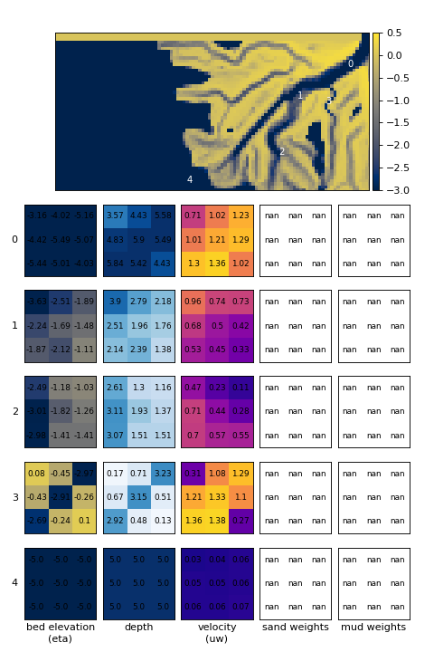
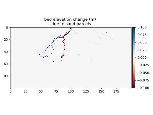
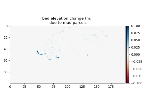
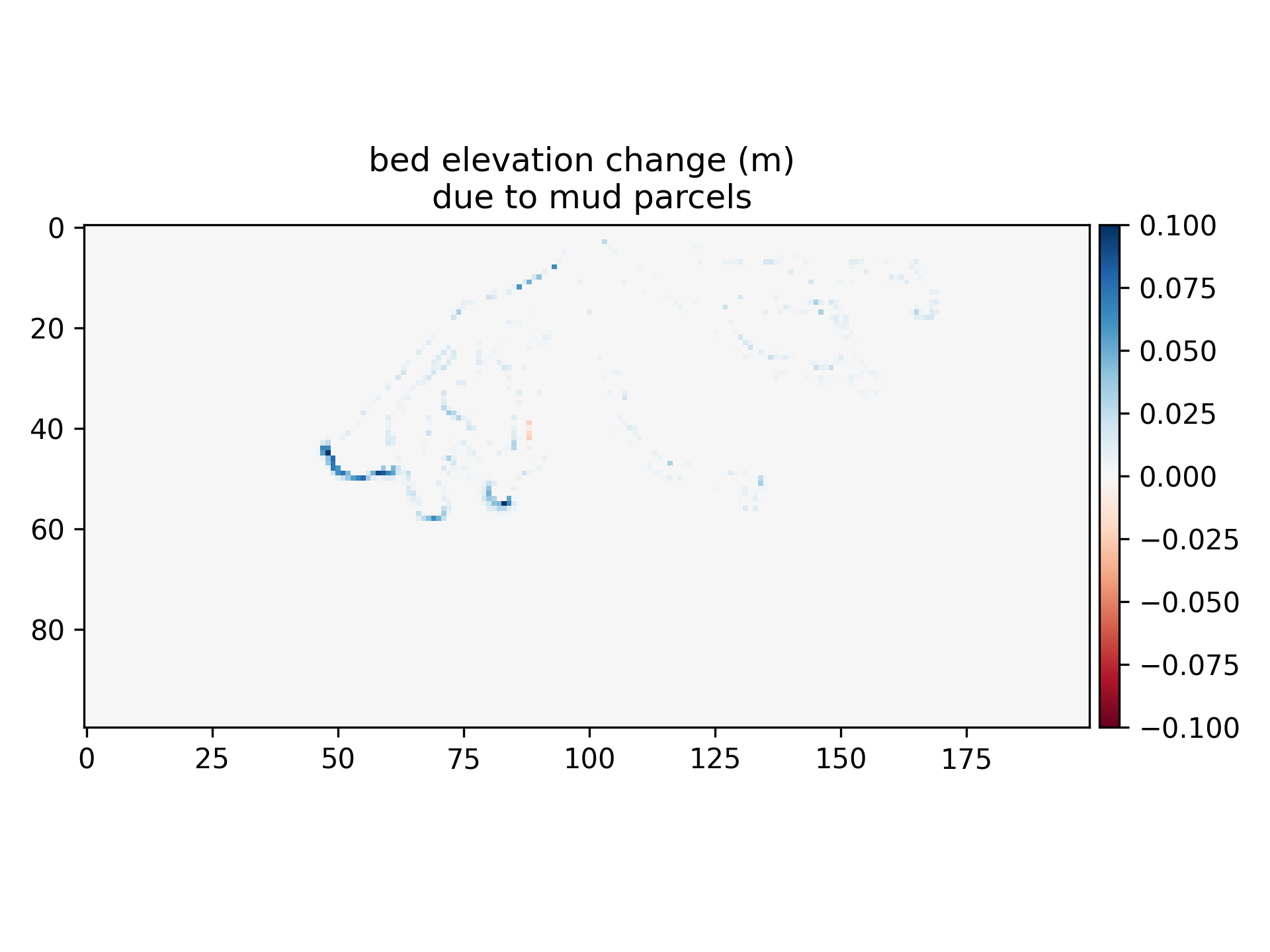
Sediment parcel routing is handled by first routing all sand parcels, applying a topographic diffusion (see below and topo_diffusion()), and then routing all mud parcels.
The impact of routing all sand and mud parcels on bed elevation is shown in the table below.
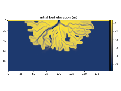
initial bed |
||
|---|---|---|
|

|

|
Model Stability
Model stability depends on a number of conditions. At its core though, model stability depends on the bed elevation rate of change over space and time. Rapid and/or abrupt bed elevation change trigger numerical instability that can occasionally run-away and cause model runs to fail. A number of processes are included in the DeltaRCM framework to help limit the possibility of failed runs.
Reference Volume
The reference volume if the foundational unit (\(V_0\)) impacting model stability. This value characterizes the volume on one inlet-channel cell, from the channel bed to the water surface:
where \(h_0\) is the inlet channel depth (meters) and \(\delta_c\) is the cell length (meters).
Time stepping
Perhaps most important to model stability is the model timestep. Recall that for each iteration, the number of parcels and input sediment discharge (as h0 u0 (c0_percent)/100) are set by the user (fixed). Therefore, to control stability, the duration of time represented by each iteration (i.e., the timestep) is determined such that changes in bed elevation per iteration are small. The model timestep is determined as:
where \(N_{p,sed}\) is the number of sediment parcels, \(dV_s\) is a characteristic sediment volume, based on the reference volume and inlet width as \(dV_s = 0.1 N_0^2 V_0\), where \(N_0\) is the number of cells across the inlet.
Limiting bed elevation change
At each sediment parcel step, bed elevation change is limited to 1/4 of the local flow depth.
Additionally, an edge case where repeated channel bed deposition creates a local depth < 0 is restricted by enforcing zero deposition if the depth < 0.
These regulations are implemented in the BaseRouter class, as _limit_Vp_change.
Topographic diffusion
Abrupt change in bed elevation (i.e., steep local bed slope) may lead to numerical instability. To prevent this, a topographic diffusion is applied immediately following the routing of all sand parcels in the model sequence.
Hint
Topographic diffusion is applied between routing sand parcels and routing mud parcels.
In implementation, topographic smoothing convolves topography with 3x3 cell kernels configured to a diffusive behavior.
The diffusion is repeated over the entire model domain N_crossdiff times.
In the following example, N_crossdiff takes the default value.
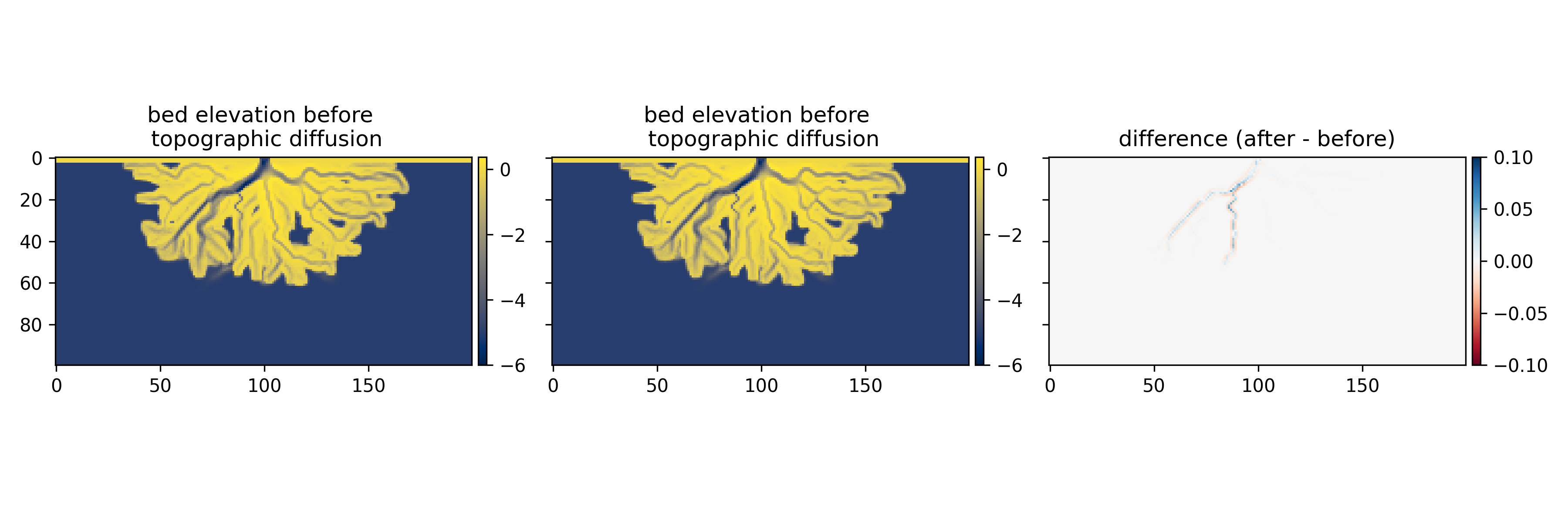

The impact of topographic diffusion is minor compared to the bed elevation change driven by parcel erosion or deposition (sand and mud routing effects).
Gamma parameter
A common source of numerical instability is with the gamma parameter.
The gamma parameter (\(\gamma\)) influences water routing weights.
A common issue arises when the domain size is increased, and \(dx\) is increased commensurately to keep overall grid count approximately constant. This results in the calculated value of \(\gamma\) increasing, because during model instantiation:
$\gamma$ partitions the importance of the water surface gradient and flow inertia in setting the “average downstream direction of flow” through a cell $\mathbfit{F}$ as:
where \(\mathbfit{F}_{sfc}\) and \(\mathbfit{F}_{int}\) are unit vectors calculated from the water surface gradient and water discharge field (i.e., inertia), respectively.
When \(\gamma\) is too large, the water surface elevation exerts a significant control on the downstream flow direction, which results in a “focusing” of flow down a single-cell-wide path.
Hint
The error beginning “Water sum(weight) less than 0.” is commonly a result of too large of a \(\gamma\)
Notes for modeling best practices
Stop simulations before the delta reaches the edge of the computational domain. Delta channel dynamics are changed when a distributary channel reaches the domain edge, because sediment is conveyed to outside the computational domain where it no longer feeds back on channel development. Channels become “locked” in place in this scenario [2], because the domain edge is an infinite sediment sink, and therefore rendering invalid any assumptions about stationarity of delta dynamics and/or stratigraphy. Moreover, the downstream water surface boundary condition (H_SL) will be violated if a channel reaches the domain edge. Generally, simulations that reach the edge of the domain should be discarded.
Stop simulations before the delta reaches a condition where the topset slope is equal to the background slope parameter (S0). When the background slope is reached, the transport capacity of sediment through the delta is diminished such that channels “clog” up and trigger model instabilities. This is really only an issue for large domains run for long duration.
Use a sufficient number of water and sediment parcels (> 2000). Too few parcels will result in a rough water surface, irregular sediment deposition, and a rough bed elevation.